 Home - Features - Downloads - Schematics - I/O Registers - Memory Map - Leave a Message |
|---|
|
ZX-Badaloc Reloaded
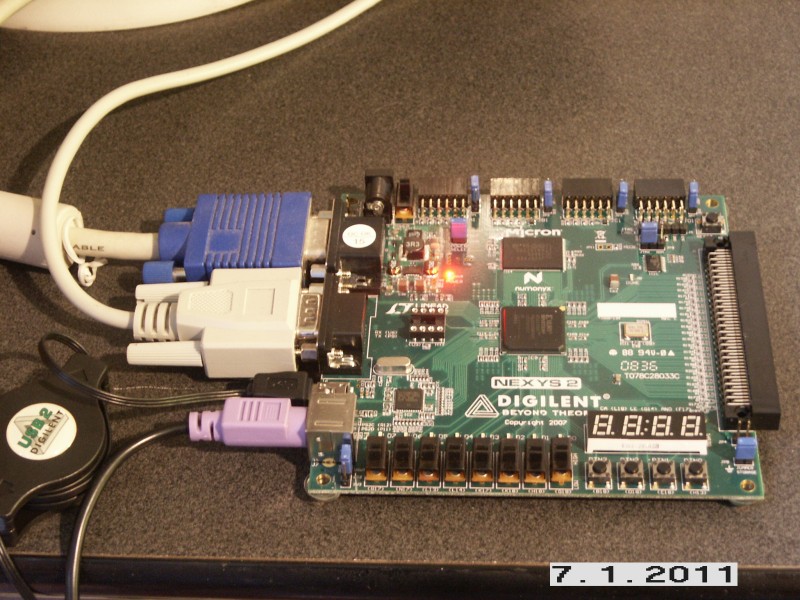
A Spartan-3E FPGA implementation of the ZX-Badaloc Spectrum clone Clone quick setup on Nexys2 Spartan-3E Board
The board can run this setup as it is, without the need of any external custom additional hardware. All you need is: a VGA monitor and PS/2 Keyboard attached to the proper board's connectors; a male/female 9 pin RS-232 cable with pins 2/3 straigth (not crossed) connected to a PC running Windows. The male end of the cable should be plugged in the 9-pin female connector on the board.
STEP 1: Configure the FPGA: Generally speaking, FPGA
configuration may be accomplished by a JTAG cable using the Xilinx
Impact software. This would also require a 5V power supply to be
connected to the board's Power Socket and the "Power Select" jumper in
"WALL" position. However, the easiest way for the Nexys2 is using the
Digilent's provided USB cable and "Adept"
software package, which can be downloaded from the Digilent web site. This is the method
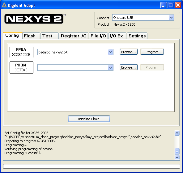
described in this tutorial. 1.A Download the badaloc_nexys2.bit file 1.B Make sure that the "MODE" jumper is in "JTAG" position (and NOT in "ROM" position) and "Power Select" jumper is in "USB" position. 1.C Before connecting the board to the USB port, download the "Adopt" software from Digilent web site and install it. 1.D Connect the USB cable to your computer and switch on the board, that will be detected by operating system.
1.E Start the Adept software, select the downloaded .bit file and press "Program" as shown in this screenshot:
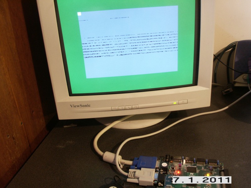
A tiny bootloader embedded into the FPGA code will be executed by the Z80 (T80 core) processor and the screen will start cycling 8 colors on the "Border" (a word that may sound familiar to zx-spectrum users). Also, a 24 bit counter used for color cycling will be visible on the screen, because it uses 3 video memory locations. A portion of the video memory is used to store the Z80 bootloader code:
Led LD0 will light up, indicating that the 'context switch' logic is active. The context switch is a special memory mapping introduced on the CPLD-based clone which allows fast bank switching for NMI service even when the active ROM does not provide a handler (for example, the ZX-Spectrum Basic ROM). The handler in the bootrom firmware allows snapshots and many other functions. Every
8 cycles,
the bootloader will attempt to load a 16K ROM image from an external
SPI Flash
chip at address $0F0000 into internal FPGA blockram. If the first byte
is not $F3 or the SPI flash is not present (as in our case, since it is
an external device) the boot is aborted. During this color cycling,
RS-232
command can be issued. We will use the RS-232 cable to upload a ROM to
the clone and start playing.
STEP
2: Quick Test: Uploading
a Sinclair ROM to the clone using the ZX-Com software: 2.A Download the ZX-Com program and start it. 2.B In the ZX-Com main window, select "3E-500 FPGA ZX-Badaloc Reloaded" in the "Hardware Type" under the "Options" menu. 2.C Using the "Serial Bootload" option from "Fpga"
menu (which is the only usable menu' when the clone is in the tiny
bootloader), upload any 16K Sinclair ROM file, for example the image of
the original 16/48K machine. Your
zx-spectrum clone will now start and display the Sinclair logo at
bottom of the screen. The PS/2 keyboard can be used to write basic
programs. List of useful buttons: BTN0: FPGA
reset: will go back to the tiny bootloader SW0: when turned ON, disables the SPI Flash boot attempt of the tiny bootloader. Useful for issuing RS-232 commands to the tiny bootloader when a ROM is already programmed into the SPI Flash. Without any mass-memory storage capability, the clone is of very little use. Step 2, however, was just a quick test to see how thing are working.
STEP 3: Testing a really working system: Instead of just uploading a Sinclair ROM, we will now send the bootrom firmware to the clone and then load a Sinclair rom on top of it. This will allow interaction with ZX-Com, like sending and receiving snapshots by RS-232: 3.A Download the Bootrom Firmware and unzip the ROMIMAGE.ROM file. 3.B As you already didin STEP 2.C, use the "Serial Bootload" option in the "Fpga" menu of ZX-Com program to upload the file to the clone. If everything went fine, you will get the main bootrom menu on the screen. Since no SPI flash nor sd-card are connected, the menu is almost useless. 3.C Select the "Upload 16K ROM" option in the "File" menu' . Browse to a Sinclair ROM (there are a couple in the zx-data subdirectory) then press "Open". The rom is uploaded into the clone's memory in rom bank 0 and then launched. If everything went fine, you will have the Sinclair logo on your screen. LD0 is turned off because the system is running the "user" rom, not the bootrom firmware. This is the normal clone operation: the Z80 executes a Sinclair ROM off the board's ram chip while the bootrom firmware sits in the background, into a FPGA's 16K block memory, waiting for an NMI signal: this allows the zx-com program to to interact with the clone, allowing memory/registers inspection and even saving/loading a freezed state of the machine into "snapshots". Here
you can find a snapshot modified to use a ROM in rom bank 0, like the
one just uploaded. Go to the "Upload Snapshot" in the "File" menu' to
upload it to the clone, then enjoy! STEP 4: Programming the FPGA configuration file into the board's Platform Flash, so it will start at next power-on: 4.A Go back to the Digilent's Adept software, but instead of using the "FPGA" browse button as you did before, press the browse button in the right side of the "PROM" section (see previous snapshot) then, navigate to the .mcs file included into the badaloc_nexys2.zip file you already downloaded. 4.B Press the "Program" button and wait for PROM programming to complete. 4.C When the operation completes, switch the board off and move the "MODE" jumper to the "ROM" position. 4.D Switch the board back on: after a few seconds, the clone will start again with the tiny bootloader, waiting for the bootrom to be uploaded (STEP 3.B).
Conclusions: That's all that can be done without additional hardware. Adding external hardware (described in the "Schematics" section) allows the following steps: 1) The tape interface will let you load software from tape then take snapshots using the ZX-Com software and RS232; 2) The SPI flash chip will allow storing all the needed roms so the zx-com program will be no longer needed to start the machine; 3) The sd-card allows faster snapshot operation and Garry Lancaster's ResiDOS to be run on the clone; 4) The programmable
joystick is a programmable joystick. All these devices will be described soon. A section with SPI flash programming (ROM layout) will be added as well.
|